Local Linkage - Program an Output to Follow an Input
A basic Local Linkage example is to program an output on the system to follow an input, so that when the input goes active the output automatically goes active. When the input goes inactive then the output also goes inactive.
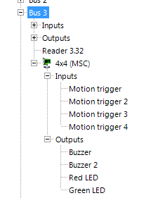
Prior to beginning the Local Linkage Setup, ensure that you have selected, renamed, and configured the relevant input(s) and output(s) in the system hardware tree.
Procedure Setup
- On the main ribbon click the Local Linkage icon.
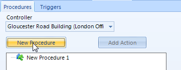
- To add the procedure, first select the controller from the available controllers drop-down list then click the New Procedure button.
The procedure is what you want to happen; the first thing to be defined is to activate a chosen output.
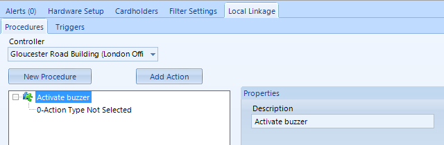
- Highlight the new procedure and enter a description.
- The Description text field allows you to change the name of the procedure from the default name and can accept any character up to a maximum of 50 characters.
- The New Procedure button adds a new procedure to the tree view and automatically selects the item. Use the add Action button to add action items to the procedure.
- The Add Action button adds a new procedure action to the tree view under the selected procedure and automatically selects the item. Use the action type selections to change the type of action. This button is only enabled when a procedure is selected.
- With the procedure highlighted click Add Action.
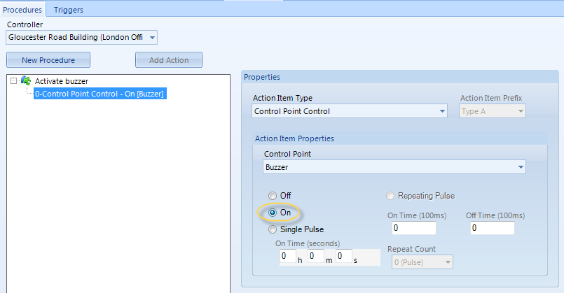
- Click on the Action, then from the Action Item Type drop down list, select 'Control Point Control'.
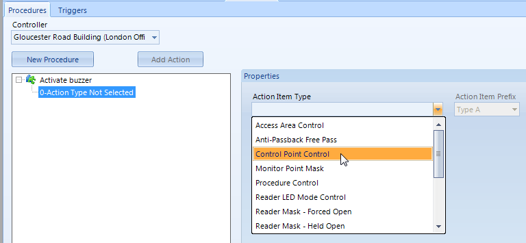
- Control Points are outputs and for this example it is using an output on a 4x4 module - wired into an NXT Mercury Powered 4-Door controller. The 4x4 module provides 4 general purpose inputs and 4 general purpose outputs - The first of these outputs has been named Buzzer - this is the output that will be used. Simply select the output from the list and set it to 'On'.
- Before defining how to trigger the procedure you also need to configure a normal state for the output to return to (when the input trigger becomes inactive). Add a second Procedure, add an Action again and then select the same output, but this time set it to 'Off'.
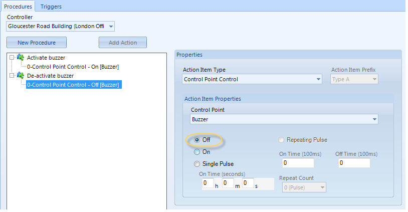
There are now two different procedures (one to activate the output and one to deactivate it).
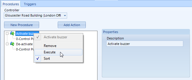
- If the hardware is online at this point you can right-click on the first procedure and choose 'Execute' and the chosen output relay will activate.
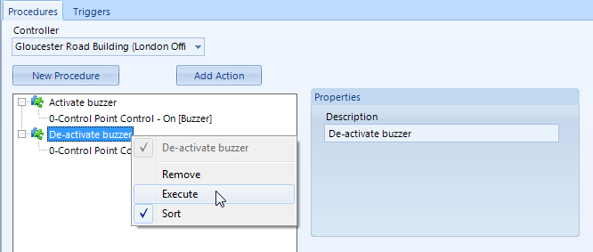
- Right-click and 'Execute' the second procedure to deactivate the same output.
Trigger Setup
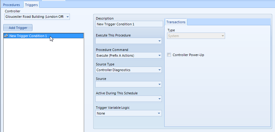
- Click on the Triggers tab next. The same controller should already be pre-selected in the controller list, so click the Add Trigger button and then highlight the new trigger.
- The trigger will also come from the same 4x4 module - one of the available inputs is named 'Motion trigger'. There are 2 procedures that need to be defined and 2 triggers.
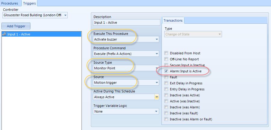
- The first trigger will activate the buzzer output when it goes active. The second trigger will deactivate the buzzer when the input goes secure.
- Rename the first trigger to something meaningful and make the following selections.
- The Description field allows you to change the default name of the trigger to something more meaningful.
- The Execute This Procedure drop down selection is a list of the stored action lists at the controller.This is the procedure action list that will be executed when an event transaction completely matches the condition.
- The Procedure Command drop down selection is a list of execution options for the procedure action list. These include Abort, Execute, and Resume.
- The Source Type drop down selection is a list of the available main categories for selecting the source of the event transaction. This selection changes a number of other selections on the menu and should be selected first.
- The Source drop down selection changes based on the Source Type selection. It may be a list of all enabled readers, monitor points, control points, weekly schedules, panels, or the controller. In most cases, the "All" selection is available along with the list of enabled devices.
- The Active During This Schedule drop down selection is a list of the enabled weekly schedules. If the weekly schedule is active, then this part of the condition criteria is met and the rest of the event transaction is analyzed for further condition matches before execution.
- The Trigger Variable Logic dropdown selection will display a dialog box that allows the definition of trigger variable states necessary for this condition to execute the specified action list. A trigger variable is a Boolean variable (either TRUE or FALSE) that is stored at the controller. The trigger variable can be set to either state by an action list and can be used as part of the condition as a logical expression represented by "a AND b OR c AND d".
- The Transaction Type drop down selection is a list of transaction types associated with the selected source type. The contents of the drop down selection changes for each source type. Each selection of the transaction type changes the available checkboxes in the Transaction Tab.
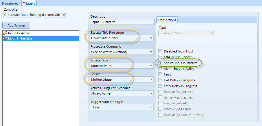
- Click Add Trigger button again. The second trigger will be the input becoming inactive ('Secure: Input is Inactive), this trigger will automatically execute the procedure to de-activate the buzzer output.
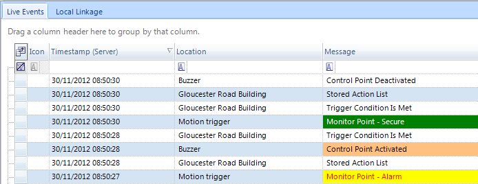
- That is the setup complete - Input 1 activates output 1 when in alarm state and de-activates output 1 when in secure state. Live Events are also posted when the Local Linkage action occurs.
Related Topics