NXT Mercury Powered Controller Setup
Note: The black colored controller PCBs are the newer controller types but these are completely backwards compatible with the older green colored controller PCBs.
1.0 Introduction
Doors.NET installation and configuration is a three step process. Each of these steps is covered separately in the help file and there are also separate standalone documents available:
- Doors.NET Software Installation (document P/N: 01565-001)
- License Manager and Gateway Configuration (document P/N: 01565-002)
- Basic Mercury-Powered NXT Configuration (document P/N: 01238-003)
This section covers the basic configuration of NXT Mercury Powered (NXT-MSC) controllers in Doors.NET software. It assumes Doors.NET has already been successfully installed and licensed on your host PC and the MSC gateway has been configured.
Before adding the MSC controller, you should make a note of the controller's MAC address. The MAC address can be found on the white sticker in the lower right corner of the controller (near to communication port 1). It will begin with 00-14-34.
2.0 Detecting the MSC Controller
When the MSC controller is powered-up and connected to the local area network (or directly to your host PC via a patch cable). It will initially try and obtain a DHCP IP address. If no DHCP address is assigned to the controller (i,e if DHCP is not enabled on the network, then the controller will automatically set itself to a static IP address.
This following section covers both IP assignment methods and then explains how to log into the controller to change its IP address.
2.1 Using DHCP IP Address Assignment
- Ensure the controller is powered-on and connected to the network.
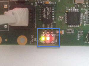
- In the lower-left corner of the controller PCB there are 3 network LEDs (when the controller is connected to a network D21 should be solid green, D22 should be solid red and D33 should be flickering red)
- Open the Doors.NET login window by clicking the client icon on the desktop.

- Login using the default username and password of admin/admin.
- Once logged in, go to Setup >> Hardware Setup then the All tab.

- You will see the MSC gateway at the top of the hardware tree.
- Right-click the gateway and select Scan or click the scan icon on the hardware ribbon bar.

- There is a utility automatically built into the MSC gateway that will scan for all MSC controllers.
- Proving the host PC has an IP address in the same range of the controller's DHCP address, the MSC controller should appear almost immediately.
- If there are multiple controllers look for the MAC address that matches the one you have noted down.

2.2 Using a Static IP address Assignment
If the network the controller is connected to does not have DHCP (Dynamic Host Configuration Protocol) then the controller will automatically set itself to a static IP address in the range of 169.254.X.X, so the last 2 segments of the address could be anything, for example: 169.254.10.55. To connect and add the controller you will have to set the host PC IP address within the same IP range.
- From Control Panel go to Network and Sharing Center.

- Click the Change Adapter Settings link.

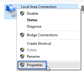
- Right click Local Area Connection and select Properties.
- Click on Internet Protocol Version 4 (TCP/IPv4) then click the Properties button.

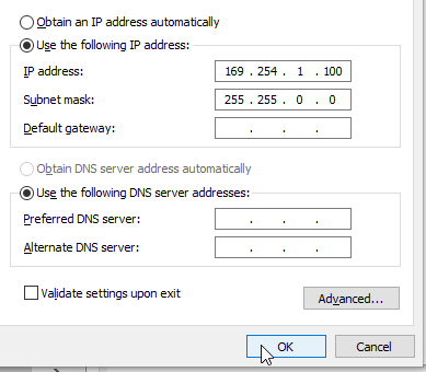
- Ensure that the IP settings are set to Use the Following IP address.
- Enter an IP address that begins 169.254. For example; 169.254.1.100
- Set the Subnet mask to 255.255.0.0
- Then click OK.
- You should now be able to scan for and detect the controller via the Doors.NET user interface.

3.0 Importing the MSC Controller
Now that the controller has been assigned with its desired static IP address it is ready to be imported. This will add the controller to the MSC gateway and it will then appear on the hardware tree.

- From the Scan Network page, click the Clear icon and it will change to Search.
- Click Search and the MSC controller should appear with its new IP address.
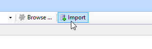
- Highlight the controller and then click the Import button.
- You will be asked if you wish to import the controller to the MSC gateway, click YES.

- Within 10 seconds you will see a second message notifying you that the import is complete. Click OK to this.

- Close the Scan Network page and return to the hardware tree.
- You will see the new controller listed beneath the MSC gateway.
- Highlight the new controller and in the controller properties you should see that it is online.

- You will see that there is a small update icon to the right of the controller
 . This can easily be cleared by performing a memory-reset on the controller. Following a memory reset a full update is sent to the controller and will take no longer than a few seconds to complete.
- Right-click the controller and select Reset >> Memory.During the reset the controller will go offline for a few seconds.
4.0 Configuring the Controller with a Static IP Address
Once the NXT-MSC controller has been imported into Doors.NET you can then access the controller's internal configuration rather than via a web browser. This section explains how to access the controller internal configuration and assign a static IP address to the controller.
Note: The default setting for the NXT-MSC controller is a DHCP setting.
- Enable Design Mode by clicking the design mode icon
 : - the title bar will state Doors.NET [Design Mode].
-
Go to Setup >> Hardware Setup >> All to display the hardware tree.
- Right click on an NXT-MSC controller on the hardware tree and select: 'internal Controller Configuration'.

-
Select the Network menu option.
- Then click the refresh button.
-
The controller settings will then appear on the right-side of the window.

- Set the Network Method to Static.
- Enter the static IP address you wish to assign to the controller.
Note: It is recommended that you ping the IP address that you wish to assign to the controller. If there is no reply from that address that that is a good indicator that the IP address is available and unassigned. If in doubt, consult the IT department.
- Change the Gateway IP address and subnet mask if you need to.
- Click the save icon to save the controller's new network settings.
- Click the button to APPLY CHANGES and REBOOT.
- The controller will now reset and the static IP address will be assigned.
5.0 Modifying the RTE Input Setting
If you are not using Request-to-Exit (RTE) inputs you will notice that the lock relays will activate when the controller has a memory reset. The reason is because by default, the RTE inputs are set to Normally-Closed. When the controller does a Power-On-Self-Test it checks the status of the inputs and if the circuits are open then the RTE function will activate. To prevent this from happening you should do the following on each reader:
- Expand the controller and then the controllers bus.
- Highlight one of the controller's readers.
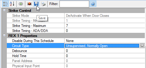
- In the reader properties located on the right, locate the REX 1 Properties.
- In the Circuit Type field change the setting from Unsupervised, Normally-Closed to Unsupervised, Normally-Open.
- Then save the reader properties.
- The next time the controller has a memory reset the lock relays will remain inactive.
6.0 MSC Controller Firmware Upgrade
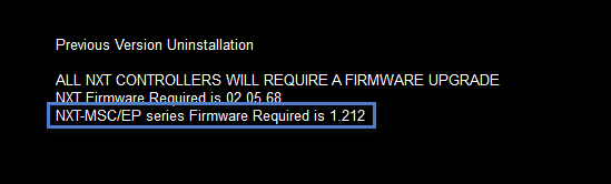
When you run the installer you will see a notification if the MSC controller firmware needs upgrading.
You will also see a notification in live events when a new controller is added to the system.

Perform the following steps to upgrade the MSC controller firmware.
Note: It takes approximately 2 minutes to upgrade the controller firmware but there is minimal system downtime because the controller will continue to function throughout most of the upgrade process. There is just a few seconds at the end of the process where the controller will not be functioning, during which time the controller will go offline then back online again.
- If a firmware upgrade is required, the required revision is listed in the Status Messages grid.
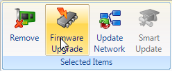
- Highlight the controller in the hardware tree.
- Click on the Firmware Upgrade icon on the toolbar ribbon.
- Windows Explorer automatically opens a window where the new firmware revision resides.
- Select the correct .CRC file and click Open.

- A notification message appears stating that the controller will go offline momentarily. Click YES and the new firmware file will be sent.

- Go to live events and you will see a Firmware Upgrade Has Started message.

- Within approximately 2 minutes you will then see a Firmware Upgrade has Completed message (followed by numerous messages that are generated as the controller performs a self test).

- Go to the Controllers grid and you will see that the new firmware version will be shown.

The NXT-MSC controller is now ready for configuration and operation
Note: Typically a firmware upgrade is to a newer version, but downgrading to an older version is allowed. However each Doors.NET software revision has minimum firmware revision requirements. Proper software and hardware operation is not guaranteed if you downgrade to a firmware revision that is out-of-date for the software revision installed.
7.0 MSC Controller LED Definitions

- D23 - Thermal Fuse LED - Should be off - If LED D23 is green then the power wires are reversed if LED D23 is red then the controller is drawing too much current.
- D25 - Power LED - Should be solid green.

- a (D21) - 10/100 status LED - Should be solid red
- b (D22) - Link status LED - Should be solid green
- d (D48) - Controller heartbeat LED - Should be flickering red
- e (D49) - Gateway communications LED - Should be slowly flickering green
- f (D50) - Bus 1 communication LED - Should be solid red
- g (D51) - Bus 2 communication LED - Should be solid green
- h (D52) - Bus 3 communication LED - Should be solid red
- i (D52) - Bus 4 communication LED - Should be solid green
- j (D1) - Bus 1 activity LED - Should be flickering green
- k (D6) - Bus 2 activity LED - Should be flickering green
- l (D11) - Bus 3 activity LED - Should be flickering green
- m (D16) - Bus 4 activity LED- Should be flickering green
Note: The bus communication LEDs will be off when there is no reader or peripheral (i.e RIM, 4x4 or GIOX) connected to the bus.
Note: The bus activity LEDs will all be solid green when the MSC controller has been factory reset and is awaiting configuration.
- n (D3) - Lock relay 1 status LED - Should be solid red when lock relay is energized
- o (D8) - Lock relay 2 status LED - Should be solid red when lock relay is energized
- p (D13) - Lock relay 3 status LED - Should be solid red when lock relay is energized
- q (D18) - Lock relay 4 status LED - Should be solid red when lock relay is energized
- t (D54) - Bus 1 over current LED - Should be off
- u (D55) - Bus 2 over current LED - Should be off
- v (D56) - Bus 3 over current LED - Should be off
- w (D57) - Bus 4 over current LED - Should be off
Note: If LED t, u, v, or w is red, that individual bus is drawing too much current and the bus is shut down to protect
the controller. When this condition is corrected, the LED will turn off and the bus will be activated.
Note: PCBs at revision F or greater have the RS-485 Bus Over Current LEDs (t, u, v, and w). PCB revisions earlier
than revision F do NOT have these LEDs.
8.0 Factory Reset Procedure

-
While the D MODE LED is still green down power the controller.
- Press and hold the white S1 button and apply the power.
-
The following LEDs will be flashing in an alternating sequence (Reset + ULED2 + ULED4) then DMODE + ULED4.
- Continue to hold down the S1 button for approximately 20 seconds.
-
Release the S1 button and the all LEDs will initially go off.
- You will see various LEDs go on and off for a few seconds then only the Reset LED will be flashing on and off.
-
The controller's ram is now reset. The 4 green LEDs to the right of the J3 jumper should also now be on.
- The controller will either be set to a DHCP address or it will automatically be set to a static address in the range of 169.254.99.X if it does not receive a DHCP address within 1 minute.
9.0 Further Setup Information
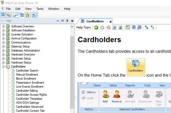
Now that the controller is added to the software you are ready to start configuring other aspects of the Doors.NET system, such as; setting up access groups and time schedules and adding cardholders. All these subjects and many more are covered in the comprehensive help file which is included with Doors.NET.
The quickest and easiest way to access the help file is to press the F1 key while on any of these screens. If you are on the cardholders screen for example (Home >> Cardholders) and then press F1, the help file will automatically open up on the cardholders section.