MR16IN (Input Control Module) Setup
1.0 Introduction
The MR16IN Input Control Module (ICM) processor provides sensor interface and output controls for security/ access control and other applications. The controller has 16 input channels for supervised contact monitoring and 2 form-C contacts for load switching. In addition, 2 digital inputs may be used for tamper and UPS status monitoring. The processor requires either 12VDC or 12VAC for power.

|

|
| Series 2 MR16-IN Module
|
Series 3 MR16-IN Module
|
2.0 Hardware Configuration
2.1 Power to the Module
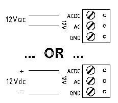
The MR16IN accepts either 12VDC or 12VAC for power. Locate power source as closed to the unit as possible. Connect power with minimum of 18AWG wires.
2.2 RS-485 Communication Wiring
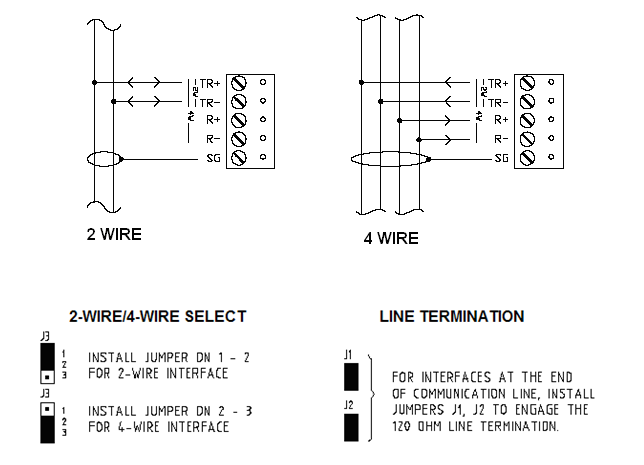
The MR16IN communicates to host via a RS-485 interface, which may be configured for either 2-wire or 4-wire operation. The interface allows multi-drop communication on a single bus of up to 4,000 feet (1,200 m). Use twisted pair(s) (minimum 24 AWG) with shield for the communication.
Notes:
- If the MR16IN module will be the last module on the 485 network set the jumpers across both pins of J1 to engage the 120 OHM line terminating resistor. If the module will not be the last on the network leave the jumper on one of the pins.
- Connect the RS-485 network to the TB10 terminal block.
- When connecting the MR16IN to an NXT-MSC controller you will need to use a 2-wire RS-485 connection.
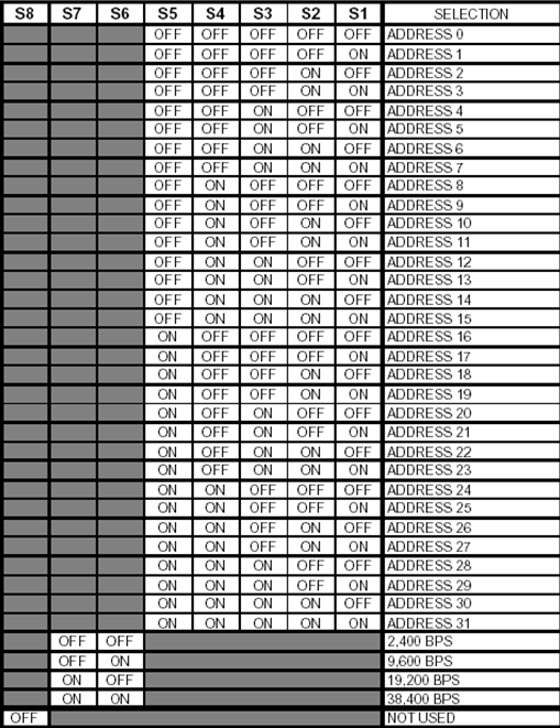
2.3 S1 DIP Switch Settings
Switches 1 to 5 select the devices communication address. Switches 6 and 7 select the communication baud rate. Communication on the RS-485 serial port is asynchronous, half-duplex with 1 start bit, 8 data bits and 1 stop bit.
3.0 Add an MR16IN to Doors.NET
To add an MR16IN to the system you must already have a Mercury EP, LP or MP controller, or an NXT-MSC controller added and online in the software.
3.1 Add to a Mercury Controller
- From Door.NET, click on Hardware >> Setup >> All.
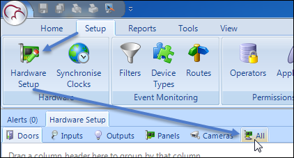
- The hardware tree will be displayed and the MSC gateway will be listed at the top. The controllers will be displayed beneath the MSC gateway.
- Expand the controller which has the MR16 module connected.
- Select the communication port which has the MR16 connected (either TB2 or TB3).
Note: Some Mercury controllers only have a TB3 port.

- Click the MR16IN icon from the SCP hardware select ribbon, if you are adding a Series 2 module.

- Or click the MR16IN-S3 icon from the Mercury Security hardware select ribbon, if you are adding a Series 3 module.

- A dialog box will appear stating the exact model (MSC- MR16IN) - you also have the option of adding multiple modules, but it defaults to adding 1.
- Click Accept and the MR16IN module will appear beneath the SPM in the hardware tree.
- If the MR16IN is configured and wired correctly it should immediately come online.
- You should also see events for the MR16IN in the live events grid.
3.2 Add to an NXT-MSC Controller
- From the hardware tree, double-click the NXT-MSC controller.
- Expand the bus that the MR16IN is connected to.
- Select the reader on that bus (by default, the reader is an NXT reader).

- Click the Hardware Browser tab located at the top of the screen.

- Click the REMOVE icon to remove the default reader.

- Select the bus which has the MR16IN connected. The bus properties will be displayed on the right.
- Change the Protocol (Serial) setting to Mercury Security.

- You will be prompted to reset the controller to enable the correct RS-485 communication protocol.
Note: The Mercury MR16IN module uses a different RS-485 communications protocol so when you have an MR16IN on the bus you cannot then have a different NXT RS-485 device on the same bus (such as an NXT reader, an NXT 4x4 module or an NXT reader interface module).
- Click YES and the controller will reset.
- Once the controller is back online, click the MR16IN-S3 icon from the hardware select ribbon bar.

Note: You can also add a Series 2 MR16IN module (green-colored PCB) by selecting the MR16IN-S3 icon.
- A dialog box will appear, giving you the option to add multiple MR16IN modules and to change the default description.
- Click ACCEPT and the MR16IN will immediately be added to the hardware tree.
- If the module is configured correctly you should see events appear from the module in the live events grid.