Doors.NET supports Elevator Control when using NXT Mercury Powered controllers and NXT 4x4 modules or GIOX units. For many different sized elevator applications this can be an extremely cost-effective solution.
Note: The NXT GIOX module is now an obsolete product but Doors.NET will still support GIOX modules which are already installed.
Using GIOX modules you can control up to 128 floors using either 2 or 4 door controllers. You can use a maximum of two GIOX modules per controller, so if they are both fully populated with 8 outputs cards each GIOX can provide control for 64 floors, giving you a maximum total of 128 floors.
One reader is situated in the elevator cab and this one reader is responsible for all access requests to all the floors. This section describes the process for configuring elevator control for up to 20 floors. It is important to follow these steps in the correct order to ensure proper operation of your elevator control system.
For a 2-door controller handling up to 34 floors:
| Floor | Device | Wiring Location | Terminal Block | Default Output Designator |
|---|---|---|---|---|
| 1 | 2D-Controller | Port 1 | TB1 | Output 0.1 |
| 2 |
2D-Controller |
Port 2 | TB3 | Output 0.2 |
| 3 | GIOX | Output Module 1 - Slot 1 | TB71 | Output 1.1.1 |
| 4 | GIOX | Output Module 1 - Slot 2 | TB71 | Output 1.1.2 |
| 5 | GIOX | Output Module 1 - Slot 3 | TB72 | Output 1.1.3 |
| 6 | GIOX | Output Module 1 - Slot 4 | TB72 | Output 1.1.4 |
| 7 | GIOX | Output Module 1 - Slot 5 | TB73 | Output 1.1.5 |
| 8 | GIOX | Output Module 1 - Slot 6 | TB73 | Output 1.1.6 |
| 9 | GIOX | Output Module 1 - Slot 7 | TB74 | Output 1.1.7 |
| 10 | GIOX | Output Module 1 - Slot 8 | TB74 | Output 1.1.8 |
| 11 | GIOX | Output Module 2 - Slot 1 | TB71 | Output 1.2.1 |
| 12 | GIOX | Output Module 2 - Slot 2 | TB71 | Output 1.2.2 |
| 13 | GIOX | Output Module 2 - Slot 3 | TB72 | Output 1.2.3 |
| 14 | GIOX | Output Module 2 - Slot 4 | TB72 | Output 1.2.4 |
| 15 | GIOX | Output Module 2 - Slot 5 | TB73 | Output 1.2.5 |
| 16 | GIOX | Output Module 2 - Slot 6 | TB73 | Output 1.2.6 |
| 17 | GIOX | Output Module 2 - Slot 7 | TB74 | Output 1.2.7 |
| 18 | GIOX | Output Module 2 - Slot 8 | TB74 | Output 1.2.8 |
| 19 | GIOX | Output Module 3 - Slot 1 | TB71 | Output 1.3.1 |
| 20 | GIOX | Output Module 3 - Slot 2 | TB71 | Output 1.3.2 |
| 21 | GIOX | Output Module 3 - Slot 3 | TB72 | Output 1.3.3 |
| 22 | GIOX | Output Module 3 - Slot 4 | TB72 | Output 1.3.4 |
| 23 | GIOX | Output Module 3 - Slot 5 | TB73 | Output 1.3.5 |
| 24 | GIOX | Output Module 3 - Slot 6 | TB73 | Output 1.3.6 |
| 25 | GIOX | Output Module 3 - Slot 7 | TB74 | Output 1.3.7 |
| 26 | GIOX | Output Module 3 - Slot 8 | TB74 | Output 1.3.8 |
| 27 | GIOX | Output Module 4 - Slot 1 | TB71 | Output 1.4.1 |
| 28 | GIOX | Output Module 4 - Slot 2 | TB71 | Output 1.4.2 |
| 29 | GIOX | Output Module 4 - Slot 3 | TB72 | Output 1.4.3 |
| 30 | GIOX | Output Module 4 - Slot 4 | TB72 | Output 1.4.4 |
| 31 | GIOX | Output Module 4 - Slot 5 | TB73 | Output 1.4.5 |
| 32 | GIOX | Output Module 4 - Slot 6 | TB73 | Output 1.4.6 |
| 33 | GIOX | Output Module 4 - Slot 7 | TB74 | Output 1.4.7 |
| 34 | GIOX | Output Module 4 - Slot 8 | TB74 | Output 1.4.8 |
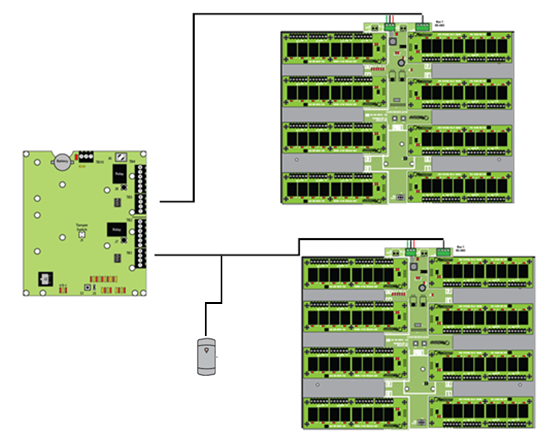
Just uses output modules. When someone presents their card the floor select buttons will illuminate for the floors to which the cardholder has access.
With this option the GIOX only uses output modules - The illustration below shows output cards on GIOX ports 1-4. Including the relays on the 2 door controllers this will provide up to 34 floors of control. If the GIOX had 8 output cards it would provide control for up to 66 floors with a 2-door controller and 68 floors with a 4-door controller.
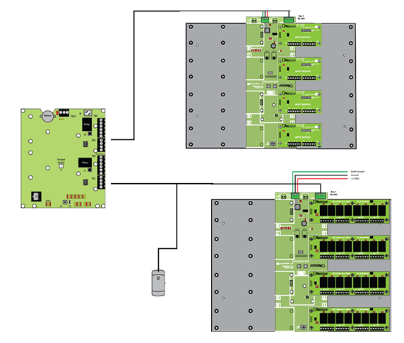
Uses input modules and output modules and requires 2 x GIOX units (one wired into bus 1 of the controller and the other wired into bus 2). The GIOX on bus 1 will have only output modules and the GIOX on bus 2 will have only input modules. This option provides transaction details about which particular floor the cardholder has selected to go to after presenting their card.
The following diagram shows the multiple GIOX modules which are required for this option. The GIOX on bus 1 has four output cards and the GIOX on bus 2 has four input cards. Again this allows up to 34 floors to be controlled. If the GIOX modules were fully populated with input and output cards it would support up to 66 floors on a 2-door controller and a maximum of 68 floors on a 4-door controller.
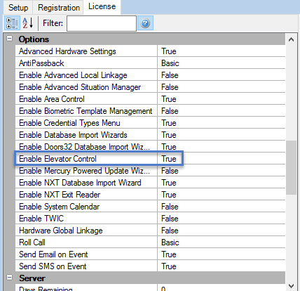
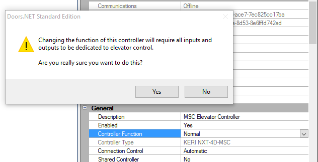
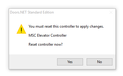
Controller Configuration Warning
NOTE: Once a controller has been configured for elevator control, it cannot be simply reconfigured to be a standard controller.
You must perform the following steps:
Please be 100% sure you have selected the correct controller to use before configuring it for elevator control.
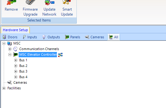
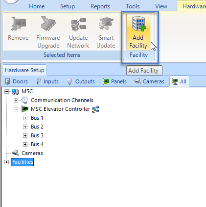
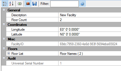
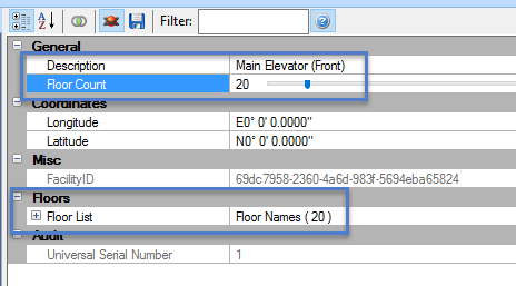
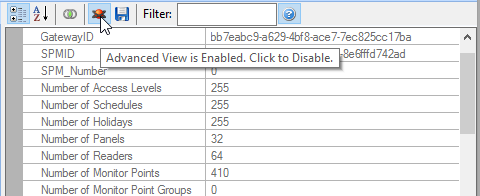
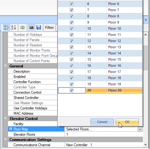
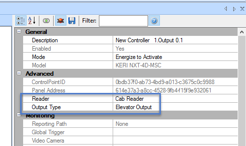
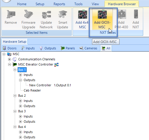
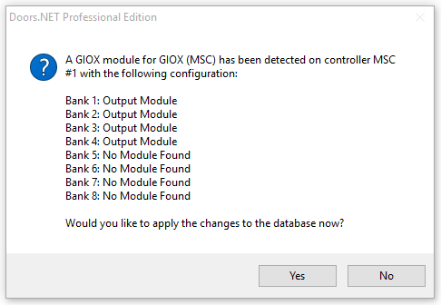
Highlight each of the buses from within the hardware tree and click 'Add GIOX-MSC.' The controller should start polling the GIOX immediately and they will appear beneath the reader(s) as shown below. The input/output configuration of the GIOX unit will be detected and displayed within a confirmation box detailing how many input or output cards are connected.
|
|
The With Floor select option only uses output/relay cards on the GIOX. When a cardholder presents their card the relays that activate will be the floors that the cardholder has access to. These outputs/relays are generally wired to the floor select buttons in the lift car. The will usually illuminate then the cardholder presses the button that corresponds with the floor they wish to go to.
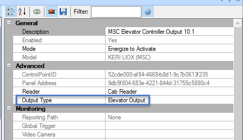
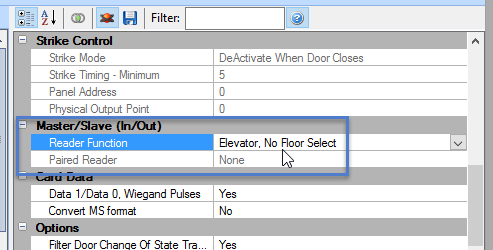
Following a valid card read, the floor relays do not automatically activate until a floor select button has been pressed. The floor select buttons are wired into input cards connected to a GIOX and when the input activates it then automatically activates the corresponding output on a different GIOX. Input for floor 1 will automatically activate the output for floor 1, the input for floor 2 will automatically activate the output for floor 2, and so on - This mapping is configured automatically when you enable Elevator Control and assign a facility. The automatic input and output mapping is for up to 66 floors when using a 2-door controller and up to 68 floors when using a 4-door controller.
Note: Using this method of Elevator Control requires the use of at least 2 x GIOX modules and then should be wired into the NXT-MSC controller as follows:
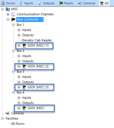
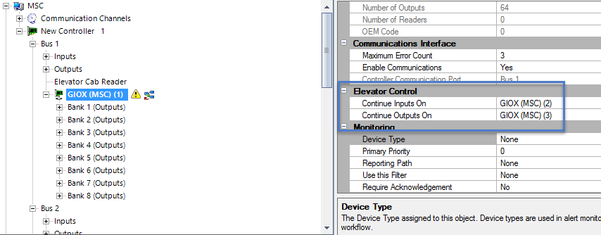
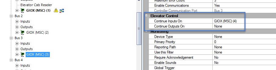
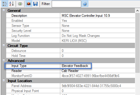
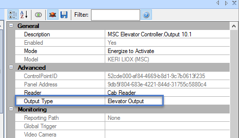
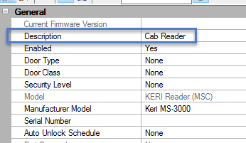
Note: As the readers on buses 2,3 and 4 are removed. It is impossible to use the controller for other standard access control functionality once it has been converted for Elevator Control.
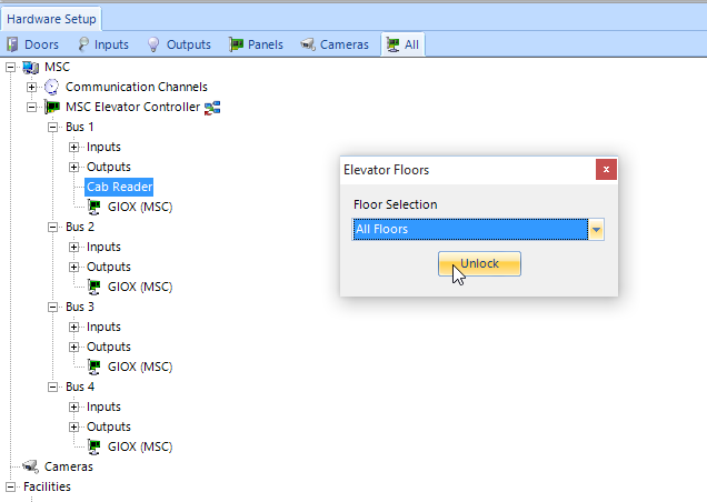
Note: The input and output cards for the GIOX are only detected when the GIOX is powered up. Therefore if you attach an output card AFTER powering up the GIOX you will not be able to command the relays because the GIOX does not know the output board(s) is present.
ALWAYS ensure the input or output cards are connected to the GIOX prior to powering it up.