
This section explains how to setup and configure all controller settings and advanced options. These settings can be found either by logging into the controller via a web browser or by accessing the controller's 'internal configuration' via the Design Mode feature. Using Doors.NET is the preferred method as it bypasses any browser restrictions or limitations and does not require you to physically be near to the controller.
The web browser interface is a secure connection that is used to configure the EP Series controller. It allows the user to:
Configure the IP address (Host Communication address);
Configure Auto-save settings;
Restore settings to factory default.
Note: If you are logging into the controller for the first time (using a web browser) you should be aware that there is now an enhanced authentication procedure that requires you to transition DIP switch S1, #1 to the off position. This will give you a 5 minute time window in which you can log into the controller using the default username (admin) and the default password (password). Once you have logged into the controller you should add a new user name and password so you can bypass this enhanced security procedure in the future.
The state of the switches on the controller determines the user information used for log on authorization, and communication parameters. By default you would set the DIP switch so that the controller uses factory default communication parameters (this gives the controller a static IP if 192.168.0.251)
| Switch | Definitions | |||
| 1 | 2 | 3 | 4 | |
| OFF | OFF | X | OFF | Normal operating mode. |
| ON | X | X | X | After initialization, enable default User Name (admin) and Password (password). The switch is read on the fly, no need to re-boot. See Special Features for more information on configuration options available with Switch 1. |
| OFF | ON | X | OFF | Use factory default communication parameters.(Address: 192.168.0.251 Port: 3001) |
| ON | ON | X | OFF | Use OEM default communication parameters. Enable “Bulk Erase” Option. See the Hardware Installation Manual for more information on “Bulk Erase.” |
| X | X | ON | X | Disable TLS secure link. Switch is read only when logging on. |
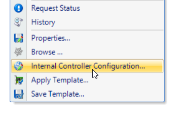
The following steps explain how to log into the controller via Doors.NET. This is the simplest and easiest method as it bypasses any browser security restrictions. You also do not need to be near to the controller and also does not require you to know the controller's programmed IP address.
These are the controller network settings that can be adjusted:
Note: Additional settings can be accessed by logging into the controller using a web browser:
This method requires you to know the controller's programmed IP address.
The Host Communication page configures the communication parameters from the host system
to the EP Series Controller.
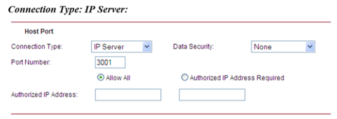
The EP1502 and EP2500 support:
Notes:
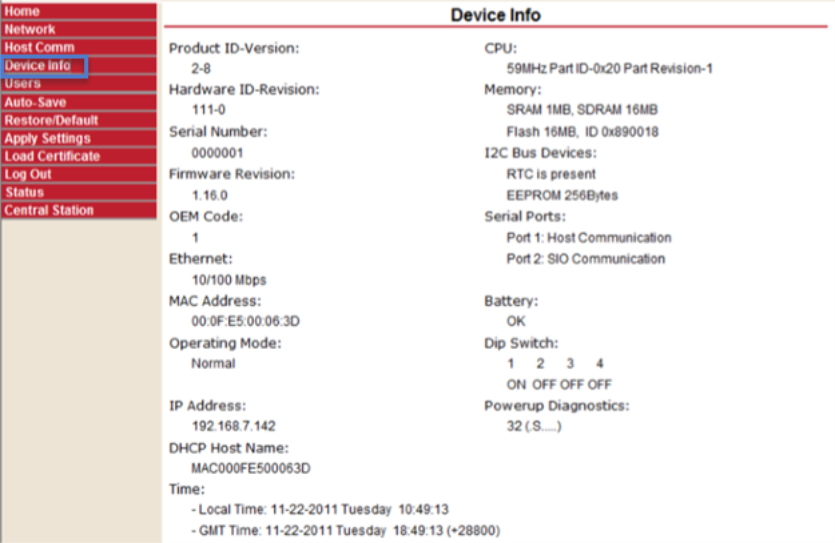
The Device Info page displays hardware and configuration settings on the controller. This pageis refreshed every minute.
The User Accounts page manages user definitions for the web interface. Users may be added, deleted or
modified from this web page. Ten users may be authorized.
Password Strength
High Password Strength – minimum of 8 characters, passes three of the password strength tests,
and password not based on user name
The following strong password requirements are based on Microsoft guidelines for creating
strong passwords.
Password Strength Tests – contains characters from any of the following categories:
Example:
The password strength is set to “Medium”, the password Gertrude is valid because it has more than 6 characters and is a combination of upper and lower case.
The password strength is set to “High”, the password Gertrude8 is valid as long as the user
name is not Gertrude.
The session timer specifies the period of inactivity before the user is logged out. The inactivity
timer can be between 5 and 60 minutes.
Note: OEM Settings can change the default settings for Session Timer.
![]() Saves any changes made to the user page other than changes made to the actual users.
Saves any changes made to the user page other than changes made to the actual users.
Special Features
See the Special Features section at the end of this document for the additional settings that are only enabled when Switch 1 is enabled.
The Auto Save page configures Auto-save behavior and determines how the controller reacts on startup if host configuration changes have been lost.
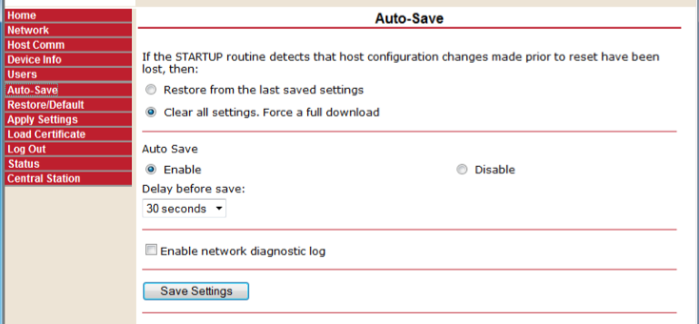
Select Restore from the last saved settings to restore from the save point at power up, or from the
re-boot button on the controller. Select Clear all settings. Force a full download. To force a
controller reload at power-up.
>> OEM Settings determine the default setting for restoring configuration after a power up, or
re-boot, and for specifying the default auto-save delay timer.
 You must click on “Save Settings” for changes to be loaded to the controller.
The Load Certificate page will allow the certificates loaded by Mercury at the factory to be replaced by unique custom certificates.
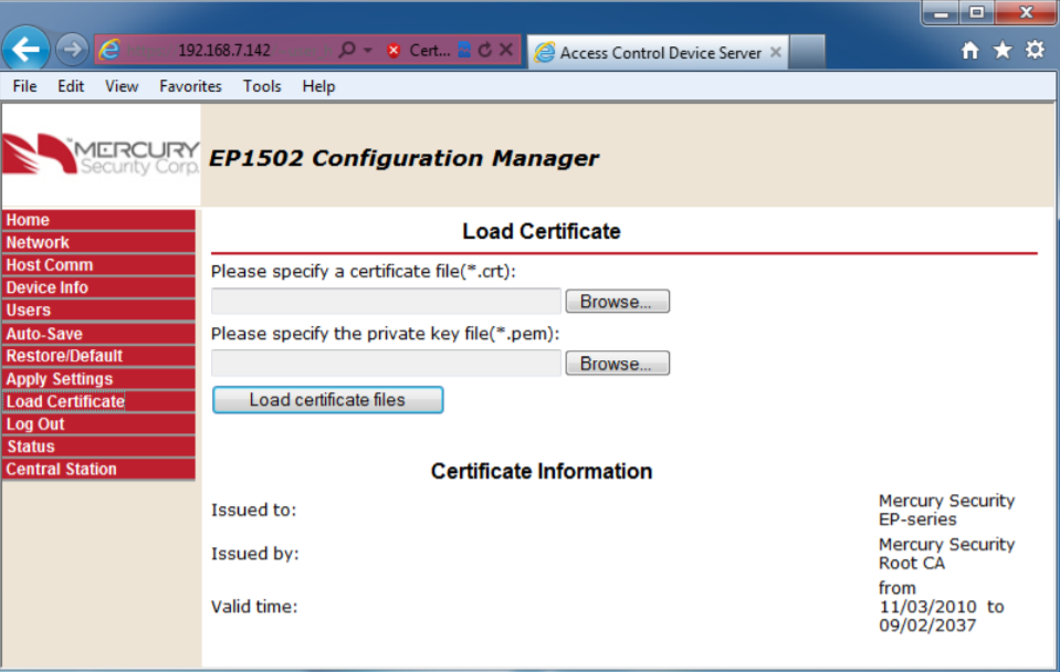
The browse buttons can be used to select the related files that will be loaded to the EP once the “Load certificate files” button is pressed.
The Certificate Information section of the page lists information about the currently loaded certificates.
OEM Settings can determine whether the “Load certificate files” button is enabled or not.
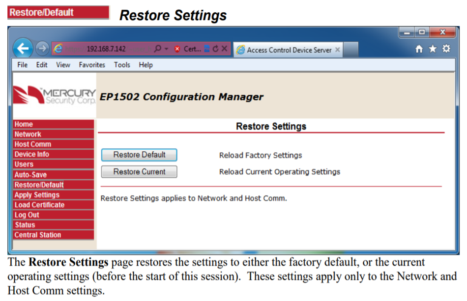
The Restore Settings page restores the settings to either the factory default, or the current operating settings (before the start of this session). These settings apply only to the Network and Host Comm settings.
 Restore the settings to factory default (192.168.0.251; IP Server; Static IP configuration).
 Restore the settings to the settings at the start of the session.
The Apply Settings page saves the Network and Comm Settings and reboots the controller.
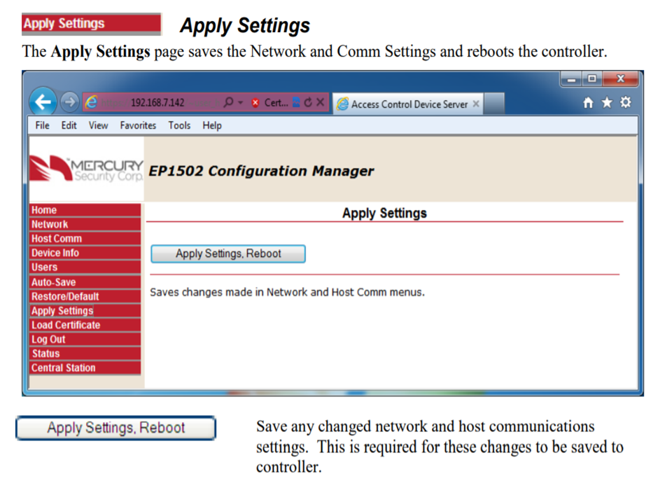
APPLY SETTINGS, REBOOT - Save any changed network and host communications settings. This is required for these changes to be saved to controller.
The Log Out link will end the session on the controller and the following page should appear.