Elevator Control via NXT-MSC Controllers
MSC Elevator Control Setup Guide Using 4x4 Modules
Doors.NET supports Elevator Control when using NXT Mercury Powered controllers and NXT 4x4 modules or GIOX units. For many different sized elevator applications this can be an extremely cost-effective solution. With one 4x4 module wired into each bus and using the four outputs on an NXT 4-door controller you can provide elevator control access for up to 20 floors per 4-door controller and 10 floors per 2-door controller.
One reader is situated in the elevator cab and this one reader is responsible for all access requests to all the floors. This section describes the process for configuring elevator control for up to 20 floors. It is important to follow these steps in the correct order to ensure proper operation of your elevator control system.
2.0 Hardware Wiring Requirements
Cab Reader
The reader situated inside the elevator cab must be wired into bus 1 of the controller for proper operation.
Alternate Elevator Cab Reader
From Doors.NET v5.2.0 onwards, you can add an alternate reader for an elevator cab (if using NXT-MSC controllers and relay elevator control). The readers used must be an NXT Entry and an NXT Exit reader. When a valid credential is presented to the Exit reader it will process the transaction exactly as if the reader was the NXT Entry reader. The Exit reader is wired into the same port as the Entry reader.
2-Door Controller and 4x4s
For a 2-door controller handling up to 10 floors:
| Floor |
Device |
Wiring Location |
Terminal Block |
Default Output Designator |
Default Input Designator |
| 1 |
2-D Controller |
Port 1 |
TB1 |
Output 0.1 |
Input 0.1 |
| 2 |
2-D Controller |
Port 2 |
TB3 |
Output 0.2 |
Input 0.2 |
| 3 |
4x4 |
Bus 1 - Port 1 |
TB22 |
Output 5.1 |
Input 5.1 |
| 4 |
4x4 |
Bus 1 - Port 2 |
TB23 |
Output 5.2 |
Input 5.2 |
| 5 |
4x4 |
Bus 1 - Port 3 |
TB24 |
Output 5.3 |
Input 5.3 |
| 6 |
4x4 |
Bus 1 - Port 4 |
TB25 |
Output 5.4 |
Input 5.4 |
| 7 |
4x4 |
Bus 2 - Port 1 |
TB22 |
Output 6.1 |
Input 6.1 |
| 8 |
4x4 |
Bus 2 - Port 2 |
TB23 |
Output 6.2 |
Input 6.2 |
| 9 |
4x4 |
Bus 2 - Port 3 |
TB24 |
Output 6.3 |
Input 6.3 |
| 10 |
4x4 |
Bus 2 - Port 4 |
TB25 |
Output 6.4 |
Input 6.4
|
- The output is the door relay for each floor.
- The input is the floor select button for each floor. Floor Select Inputs are only used/wired if the cab reader is set to Elevator - With Floor Select. Use this option when you need to know which floor the cardholder has selected; which is a different behavior than the default option of Elevator - No Floor Select.

4-Door Controller and 4x4s
For a 4-door controller handling up to 20 floors:
| Floor |
Device |
Wiring Location |
Terminal Block |
Default Output Designator |
Default Input Designator |
| 1 |
4-D Controller |
Port 1 |
TB1 |
Output 0.1 |
Input 0.1
|
| 2 |
4-D Controller |
Port 2 |
TB3 |
Output 0.2 |
Input 0.2 |
| 3 |
4-D Controller |
Port 3 |
TB5 |
Output 0.3 |
Input 0.3 |
| 4 |
4-D Controller |
Port 4 |
TB7 |
Output 0.4 |
Input 0.4 |
| 5 |
4x4 |
Bus 1 - Port 1 |
TB22 |
Output 5.1 |
Input 5.1 |
| 6 |
4x4 |
Bus 1 - Port 2 |
TB23 |
Output 5.2 |
Input 5.2 |
| 7 |
4x4 |
Bus 1 - Port 3 |
TB24 |
Output 5.3 |
Input 5.3 |
| 8 |
4x4 |
Bus 1 - Port 4 |
TB25 |
Output 5.4 |
Input 5.4 |
| 9 |
4x4 |
Bus 2 - Port 1 |
TB22 |
Output 6.1 |
Input 6.1 |
| 10 |
4x4 |
Bus 2 - Port 2 |
TB23 |
Output 6.2 |
Input 6.2 |
| 11 |
4x4 |
Bus 2 - Port 3 |
TB24 |
Output 6.3 |
Input 6.3 |
| 12 |
4x4 |
Bus 2 - Port 4 |
TB25 |
Output 6.4 |
Input 6.4 |
| 13 |
4x4 |
Bus 3 - Port 1 |
TB22 |
Output 7.1 |
Input 7.1 |
| 14 |
4x4 |
Bus 3 - Port 2 |
TB23 |
Output 7.2 |
Input 7.2 |
| 15 |
4x4 |
Bus 3 - Port 3 |
TB24 |
Output 7.3 |
Input 7.3 |
| 16 |
4x4 |
Bus 3 - Port 4 |
TB25 |
Output 7.4 |
Input 7.4 |
| 17 |
4x4 |
Bus 4 - Port 1 |
TB22 |
Output 8.1 |
Input 8.1 |
| 18 |
4x4 |
Bus 4 - Port 2 |
TB23 |
Output 8.2 |
Input 8.2 |
| 19 |
4x4 |
Bus 4 - Port 3 |
TB24 |
Output 8.3 |
Input 8.3 |
| 20 |
4x4 |
Bus 4 - Port 4 |
TB25 |
Output 8.4 |
Input 8.4 |
- The Output is the Door Relay for each floor.
- The Input is the Cab Request for each floor. Cab Request Inputs are only used/wired if the cab reader is set to Elevator - With Floor Select. Use this option when you need to know the floor that was selected; which is a different behavior than the default option of Elevator - No Floor Select.

Floor Select Options
The Elevator - With Floor Select option is used when you need the software to report the floor that was selected by the cardholder. This is a different behavior than the default option of Elevator - No Floor Select which simply provides floor access as appropriate.
- No Floor Select means all outputs will activate for all floors to which a cardholder has access when they present and authenticate their credential to the elevator cab reader. So if a cardholder has total access, all outputs will change state, which, in effect, will allow any of the floor select buttons to be pressed in the cab in order to access any of the floors. Without the Floor Select option you are only using the 4x4 module outputs. When someone presents a card the floor buttons in the elevator cab will illuminate for the floors which the cardholder has access to.
- With Floor Select does not activate any of the outputs until an input is pressed following a valid card read. Once input 1 has been pressed, output 1 will fire; input 2 will fire output 2, etc. This information is then stored in the system database so that at a later time reports can be run to see which floors cardholders have accessed. With the Floor Select option 4x4 module inputs and outputs are paired, one input for every output. There are also settings for defining the floor relay activation time and the floor select time (the time duration permitted in which a floor select button must be pressed).
Verify Your License
Begin by ensuring your Doors.NET Application Server license is configured with Elevator Control enabled. To check this, click on Start > All Programs > Doors.Net > License Manager. If it states False instead of True then you need to contact Keri Systems sales department to purchase an upgrade to your license.

Hardware Configuration
Controller Configuration Warning
Note: Once a controller has been configured for elevator control, it cannot be simply reconfigured to be a standard controller.
You must perform the following steps:
- delete the elevator facility setting from the controller
- delete the controller from the database
- RAM reset the controller
- scan the system to rediscover the controller
- add it back to the database
Please be sure you have selected the correct controller to use before configuring it for elevator control.
- Log into your client and open Doors.NET.
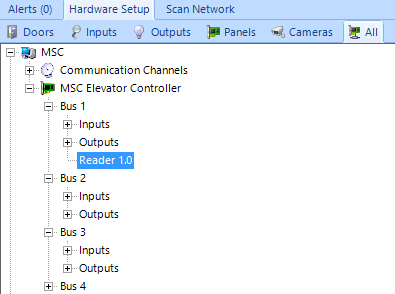
- Go to the Setup >> Hardware Setup >> All tab. The hardware tree displays the hardware gateway and controllers. The image below shows one NXT-MSC 4-door controller is added.
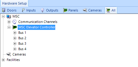
- At the bottom of the hardware tree is a node labeled ‘Facilities.’ A Facility needs to be defined and this is where you specify how many floors will be controlled. Generally a facility, in the physical sense, is an elevator shaft.
- Click on Facilities and then click the Add Facility button on the ribbon bar.

- Click New Facility and view the facility properties on the right.

- Change the description to something appropriate to your site.
- The new facility defaults to having 2 floors. Change this count by overwriting it with the number of floors desired, in this case 20. The ‘Floor List’ automatically adjusts accordingly. At this time you may also name each of the floors by clicking on the drop-down arrow then double-clicking any of the floor names listed.

- Next step is to configure the controller. Advanced View must be enabled to see all the relevant sections. Click on the desired controller in the Hardware tree and view its properties.

- In the General settings, change the controller function from Normal to Elevator. A confirmation message box appears. Click Yes.

- Further down the properties list is the Elevator Control settings. Select the facility you wish to assign to the controller.
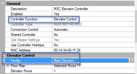
- Now assign the Floor Map; selecting which floors this controller will be servicing.
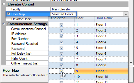
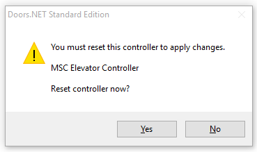
- Save the controller settings. The Floor Count is automatically set according to the information in the Floor Map. The software generates an alert stating the controller needs to be reset. Click Yes to allow the reset.
- The controller now shows the reader on bus 1 is designated as the elevator reader, the other readers on the controller are removed from the hardware tree. The output relays for each of the buses are changed from Strike Outputs to Elevator Outputs and all are associated with the elevator reader.
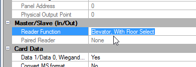
- With the Elevator Reader on bus 1 highlighted. Reference the reader properties and look for the Primary/Secondary (In/Out) settings. Set the reader to 'Elevator, No Floor Select' or 'Elevator, With Floor Select' per your application.
- Next is adding the 4x4 modules that will be used for the floor relays (and Floor Select inputs if the Floor Select option is being used).
- On the hardware tree click on the bus you want to add a 4x4 to.
- On the ribbon bar, click the Add 4x4-MSC icon.
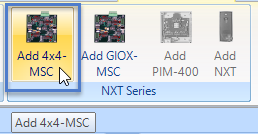
- Repeat steps 15 for each 4x4 that needs to be added to the system.
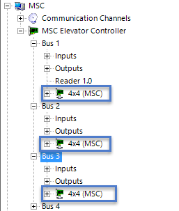
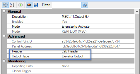
- Verify the outputs on the controller (and on the 4x4s if used) are configured correctly by expanding one of the buses then expanding the outputs. Select any output and in its properties you should see it is configured as an 'Elevator Output.'
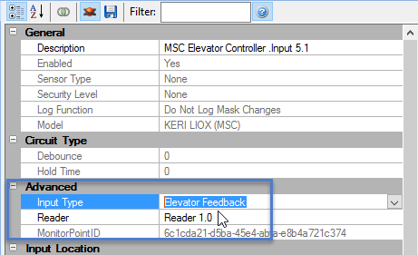
- If you are using the 'With Floor Select' feature, the door contacts on the controller will be assigned as Elevator Feedback Inputs and the RTE/REX inputs will become Unassigned. Highlight a controller input (or a 4x4 input) - in the properties it should be showing as 'Elevator Feedback'.
Note: All other reader are unavailable when a controller is converted to an Elevator Controller. For this reason a controller configured for Elevator Control cannot be used for general access control.
- Perform a Temp Unlock (All Floors) and verify the controller configuration. When this command is performed all relays should activate for the Strike Time that the reader is set to.
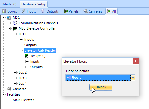
- All the configured Elevator Outputs, including those on the controller should activate. This confirms your controller has been successfully configured for Elevator Control.