AD-300 Lock Setup Guide
1.0 Introduction
Allegion Schlage AD-300 networked, hardwired locks can be integrated seamlessly with the Doors.NET software when used with the NXT-MSC (Mercury-Powered controllers). You can connect and communicate with up to 32 AD-300s via the controller's RS-485 communication buses.
The AD-series locks have extensive functionality and operating modes and are combined units consisting of the electric lock, credential reader, request-to-exit and request-to-enter sensors, door position switch and tamper guard.
For standard applications the AD-300 can be customized with a variety of credential readers including keypad, magnetic stripe or multi-technology which can read both proximity and smart-card technology.
Note: Effective from Doors.NET v5.2.0, when using NXT-MSC controllers you will need to delete the Keri NXT reader which is added to the bus by default and then configure the protocol to support the Schlage RSI protocol before adding the PIM-400.

- The maximum number of AD-300 locks per bus is 32 (if only have AD-300s on the bus).
- The maximum number of AD-300 locks you can add to an NXT-MSC 2D or 4D controller is 64.
Note: Effective from Doors.NET v5.2.0 you can mix and match ENGAGE Gateways, PIM-400s and AD-300s on the same bus. You can add up to 8 x ENGAGE Gateways, 8 x PIM-400s or 32 AD-300s. Adding one of these supported devices will reduce the number of other devices that can be added. For example, if 4 x ENGAGE gateways are added you will then be limited to adding 4 x PIM-400s or 28 AD-300s.
2.0 Hardware Requirements
2.1 NXT Hardware Requirements
- Requires the use of NXT-MSC (Mercury Powered controllers) - (Mercury (SCP), standard NXT or PXL controllers do not support Allegion wireless locks).
- The NXT-MSC controllers must be using the latest firmware (1.294) at the time of writing.
2.2 Allegion Hardware Requirements

AD-300 Lockset
|

SUS For Android App and USB cable
|
3.0 Software and Licensing Requirements
Access the License Manager to verify you have the correct license settings: Start menu >> All Programs >> Doors.NET >> License Manager.
- Current Doors.NET Software (Version 5.2.0 at time of writing)
- Mercury Powered controller licensing
- Mercury gateway installed and configured.
- Allegion enabled.
The following screen shots are the required settings within the License Manager
3.1 License Capacities
- Number of Gateways - 1 or more
- Readers - Allegion - 1 or more
- Readers - Allegion per Controller - 1 or more

3.2 Hardware Capacities
Allegion - True
Keri Systems - NXT (MSC) - True

3.3 User Interface
Distribution Interface - False

4.0 Configure the AD-300 With the Schlage™ Utility Software and Android App
The Schlage Utility Software (SUS) is an application that runs on supported Android devices. It is used to configure, edit and program all supported devices.
You can use the app to; edit the AD-300 lock properties, update the lockset's firmware, couple the HHD to the device, set the date/time and run diagnostics.
This section assumes that you have already:
- Downloaded and installed the SUS Android app.
4.1 Logging into the App for the First Time
- Once the application is downloaded, you must change default password.
- Select User Type: Manager or Operator.
- Enter Default Password: 123456.
- You will be prompted to enter a new password and confirm the new password.
>> New password must not be a default password, subset or super set of default password.
- You must log in again with User Type: Manager or Operator and new password.
4.2 Connecting the Mobile to the AD-300
This section explains how to connect the mobile device to the AD300 locks:
Note: The mobile device must have file transfer via USB enabled to function properly.
- Start the Schlage Utility Software for Android (SUS-A).
- Connect the SUS-A Cable to the mobile device. A pop-up will appear, “Allow Schlage Utility Software to access SUS A-CABLE?” Click OK to continue.
- Connect the SUS-A Cable into the lock’s USB port located at the bottom of the exterior housing.

- Press the Schlage button twice to begin communication.
- The lock will be displayed on the screen.
4.3 Couple the Mobile Device to the AD-300 Lock
AD-Series locks can be coupled, or authenticated, with the mobile device. This provides enhanced security by ensuring that the lock will only communicate with mobile device(s) to which it has been coupled. Once the lock has been coupled, the Coupling Password is passed to the device from the mobile device during programming.
Notes:
- Mobile devices with the same coupling password can program the same devices. Once the mobile device and lock are coupled, the coupling password is disabled in the lock and any mobile device with the correct coupling password will automatically couple with the lock.
- The mobile device will use a default Coupling Password (123456) when coupling with a device. The Coupling Password should be changed to provide increased security for your locks.
- If a device is not in Coupling mode, SUS-A will display a device specific message with instructions for placing the device into Coupling mode.
4.4 Steps to Couple with the AD-300 Lock
- Connect the mobile device to the lock using the SUS-A cable.
- Press the Schlage button twice. The lock will be displayed on the screen.
- On the mobile device, select Device Options.
- Remove the top inside lock cover.
- Press and hold the Inside Push button. Then press and release the tamper switch three times.
- Release the Inside Push button. On the lock, the Inside Push button LED will illuminate.
- When Coupling is successful, a message will be displayed on the screen.
5.4 Test the Lock for Normal Operation
- In the SUS app, select Device Options >> Diagnostics.
- Observe the graphics on screen, while performing the actions listed below. The graphics should reflect the action being performed.
5.5 Programming the AD-300 RS-485 Address
- On your Android device, launch the SUS app.
- Login as Manager (default password 123456)
- Press the Schlage button (on the lock) twice.
- If successfully connected the AD-300 will be listed
- Select Device Options
- Select Lock Properties.
- Select the Edit tab
- Select the RS-485 address you wish to assign to the AD-300 (All AD-300 locksets wired to a bus of an NXT-MSC controller need to be uniquely addressed between 1 and 15).
- Select Save.
- Select OK.
- Select Back.
- Close the SUS app.
- Disconnect the USB cable from the AD-300 and the Android device.
- Wire the AD-300 to the NXT-MSC controller.
 The full Allegion SUS for Android User Guide can be downloaded here:
3.0 Wiring the AD-300 to the NXT-MSC controller (2-wire half duplex)
Notes:
| NXT-MSC RS-485 port AD-300 RS-485 Port |
| PIN |
Label |
Wire Color |
PIN |
485 Connector Label |
| 1 |
12VDC |
-- No Connection -- |
|
-- No Connection -- |
| 2 |
Ground |
-- No Connection -- |
|
-- No Connection -- |
| 3 |
IO + |
Green |
5 |
TDA - |
| 4 |
IO - |
White |
3 |
TDB + |
4.0 Configuring Doors.NET with the AD-300
This section assumes the NXT (MSC) 2-door or 4-door controller is online, configured and ready to add the AD-300 lock.
(Refer to the NXT (MSC) controller Quick Start Guide for further details about setting up and configuring this controller type with Doors.NET).
Note: Effective from Doors.NET v5.2.0, when using NXT-MSC controllers you will need to delete the Keri NXT reader which is added to the bus by default and then configure the protocol to support the Schlage RSI protocol before adding the PIM-400.
- Log into the Doors.NET software and go to Setup >> Hardware Setup >> All.
- On the hardware tree you will see the gateway node and the NXT (MSC) controller(s).
- Expand the controller and select the bus which the AD-300 is wired into.
- Select the reader which is added to the bus, by default.
- Click on the Hardware Browser tab at the top of the screen and click the Remove icon.

- The default reader (NXT-3R) will be removed from the bus.
- With the bus still selected, locate the Protocol (Serial) setting in the bus properties.
- Change the protocol (Serial) setting from Keri Systems to Schlage RSI.

- Save the bus settings.
- You will be prompted to reset the controller.
- From the hardware ribbon, with the bus selected, click the Add AD-300 icon.

- Click the ACCEPT button and an AD-300 will appear on the hardware tree.

- Right-click on the NXT-MSC 2 or 4 door controller and select Reset >> Memory.
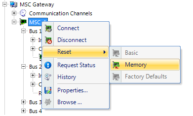
- Within a few seconds the AD-300 will then be showing as online.

5.0 Setup and Configuring Credential Types
Before setting up users or adding credentials to users, “Credential Types” must be configured to allow proper card and/or PIN operation. The Credential Types feature must be enabled on your license key within the Options section.

- While logged into the Doors.NET software, click Setup >> Credential Types.
- From the Access Control tab, click Add Active Format.
- In the properties pane locate Format and select Standard 26-bit.
- For PIN operation leave the FC field set to 0. and leave the Offset field set to 0. (This format will allow the keypad to work in 26-bit mode with a FC of 0).
- For CARD operation set the FC field to the Facility Code programmed in the card(s) to be enrolled.
- Leave the offset field set to 0, click save.
- If using cards the above process will need to be completed for each facility code in use.

Enrolling a Card or a PIN
- From Home >> Cardholders, add a new cardholder and save.
- When adding a card or PIN to a cardholder ensure the 'Calculate Internal Number' option is unchecked.
- Enter the Imprint number (number printed on the card) or the PIN into the Cardnumber field.
- Leave the issue code at the default value of zero.
- Click the Add Card button then save.
- Assign the card record an access group from the Access Rights tab.
- This card will automatically be sent to the controller(s) and should work within a few seconds.
Features and Benefits
Supported Card Formats
Proximity cards (125kHz)
-
AWID®
- GE/CASI®
-
HID®
- Schlage®
-
XceedID®
Smart cards (13.65 MHz)
-
aptiQ™ MIFARE Classic
- aptiQ™ MIFARE DESFire™ EV1
-
PIV and PIV-I compatible
Smart cards (13.65 MHz) - Reads card serial number only):
-
HID iCLASS®
-
DESFire®
- MIFARE®
-
MIFARE DESFire™ EV1
Resetting the AD-300 to Factory Defaults
This will remove all information programmed in the lock. Lock settings that will be deleted include functions, failure mode and re-lock delays however, this will not reset configurations and settings in the reader (such as credential format, magstripe reader track and beeper default).
- Remove the top inside cover.
- Press and hold the Schlage button until two (2) beeps sound (10 seconds).
- Release the Schlage button.
- Press and release the Inside Push Button (IPB) three (3) times within 10 seconds. One beep will sound and one red blink will occur with each press.
- The Schlage button and IPB will both light green for 1 second and a one-second beep will sound to confirm that the lock has been reset.
Note: If the PIB is not pressed 3 times within 10 seconds, two beeps with two red blink indicate timeout.
- Replace the inside top cover.
Click here to download a standalone PDF of this document (P/N: 01671-001 Rev C).